Elevator Wire Rope: The Ultimate Guide to Selection, Safety, and Maintenance
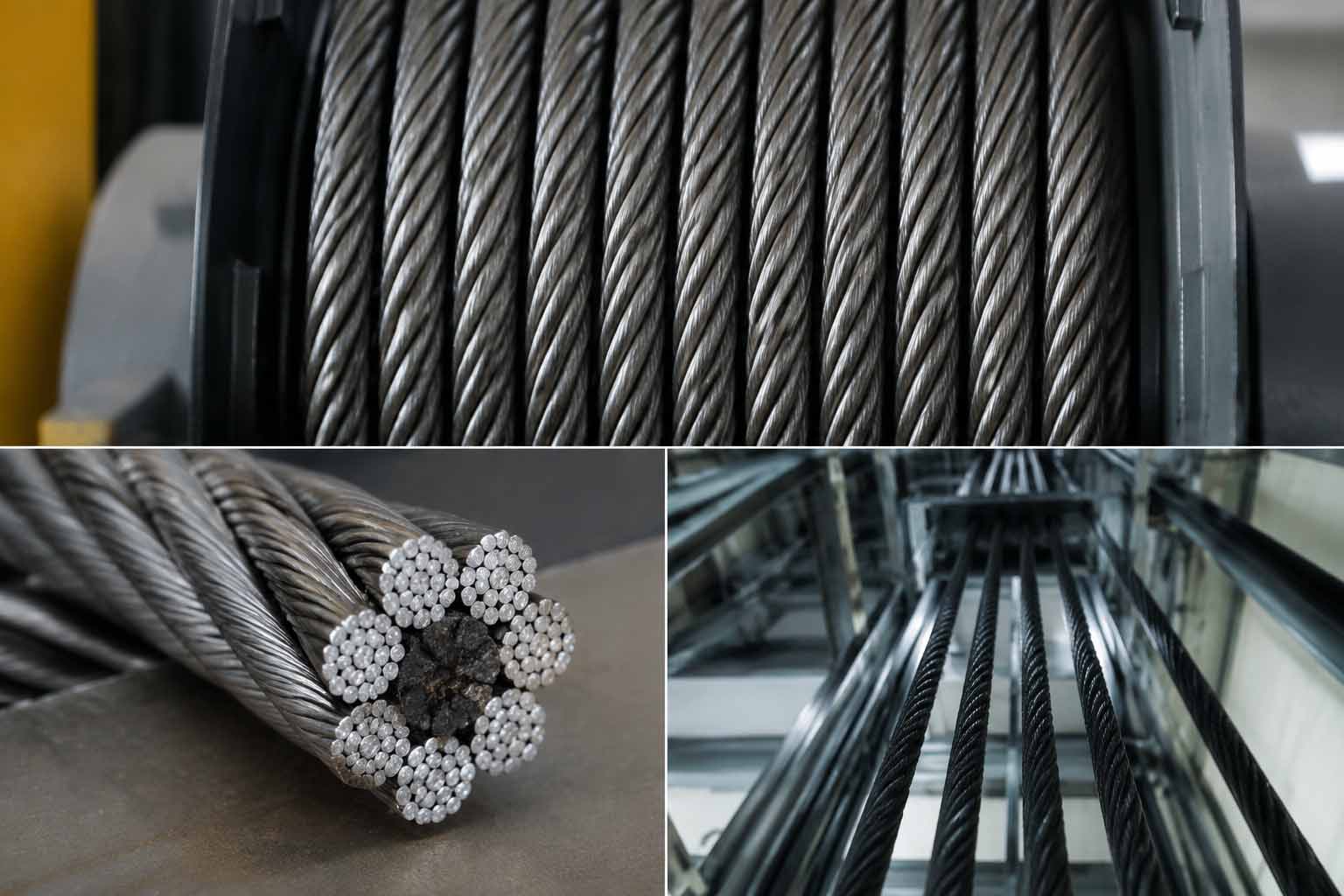
The elevator wire rope (elevator steel rope)is the primary load-bearing component in vertical transportation. It suspends the cabin, transmits motor torque, and engages safety mechanisms. Operating under continuous tension and high-frequency bending fatigue, these components require precise engineering and strict maintenance.
This technical guide details the specifications, mechanics, and maintenance protocols for suspension systems. It covers traction calculations, international safety codes, structural anatomy, and discard criteria. Engineers, facility managers, and procurement specialists can use this data to specify, maintain, and replace an elevator wire rope safely and efficiently.
A Brief History of Wire Elevator Ropes
Early vertical lifting systems utilized hemp ropes or iron chains. Hemp degraded rapidly from moisture. Iron chains suffered from sudden, unpredictable failure at single weak links.
In 1834, Wilhelm Albert invented the first wire rope for mining. He twisted metal wires into strands, and twisted those strands around a core. This introduced mechanical redundancy: if one wire failed, the remaining wires maintained the load.
In 1852, Elisha Otis invented the elevator safety brake. This made passenger elevators viable, but early puddled-iron ropes limited building heights. By the late 19th century, manufacturers transitioned to cold-drawn, high-carbon steel. This material drastically increased the tensile strength-to-weight ratio.
Modern production now controls carbon content at microscopic levels. Advanced patenting (heat treatment) processes and synthetic core materials allow current elevator wire ropes to bend millions of times over motor sheaves at speeds exceeding 20 meters per second.
→A Brief History of Wire Elevator Ropes: From Iron to High-Tensile Steel
Anatomy and Core Construction of a Wire Rope
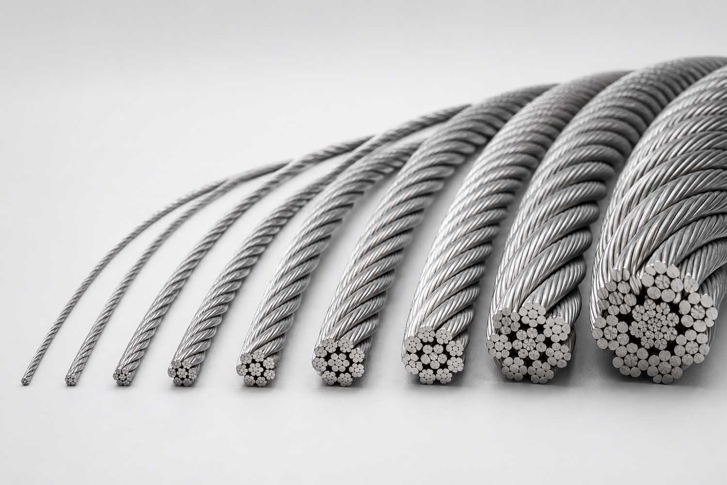
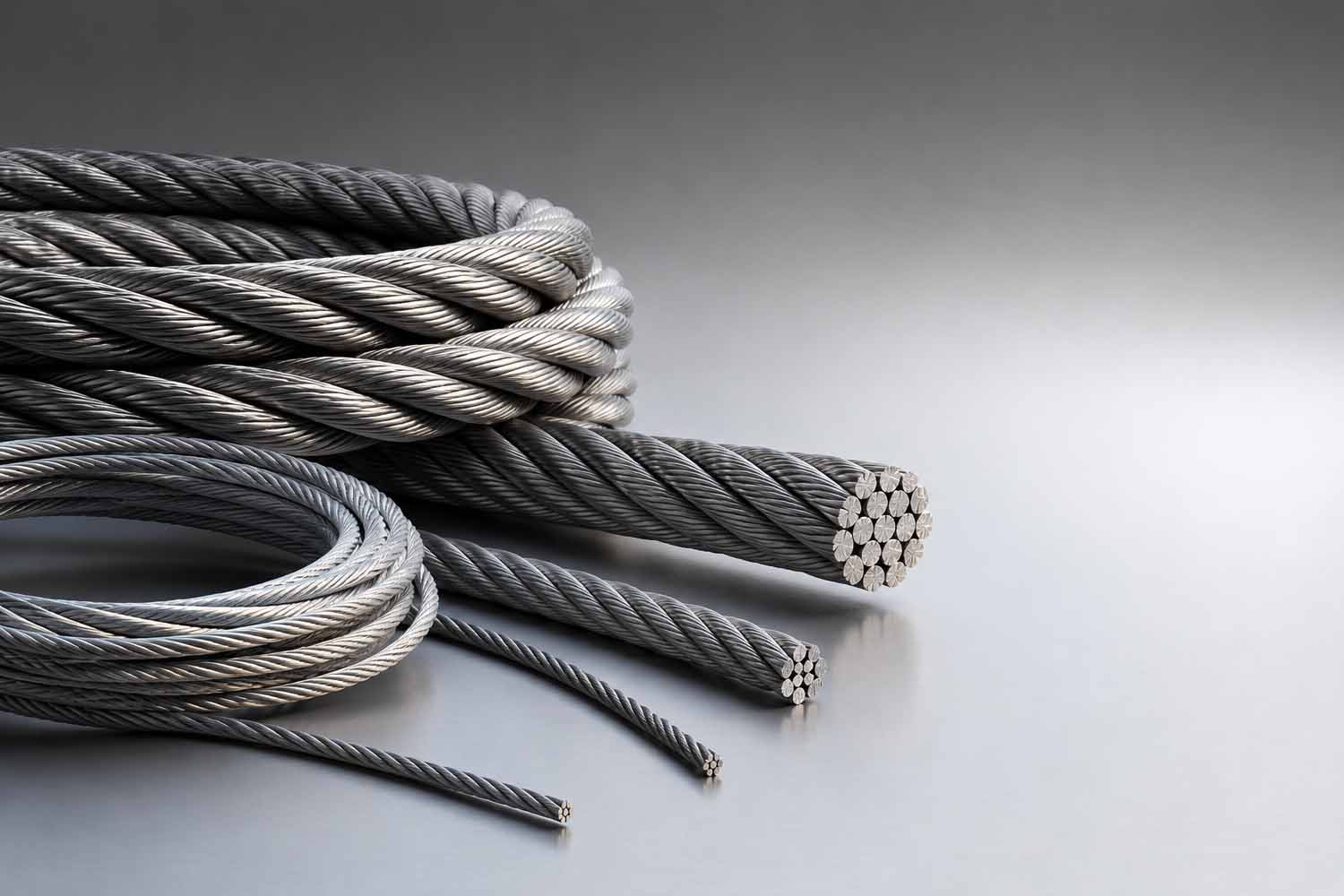
An elevator steel rope is a complex mechanical assembly. It consists of three structural elements: wires, strands, and the core.
1. The Wires
Wires are cold-drawn from high-carbon steel (typically 0.4% to 0.8% carbon). Drawing steel through progressively smaller dies aligns the grain structure, maximizing tensile strength. Manufacturers use "dual-tensile" configurations to balance flexibility and strength:
- Outer Wires (e.g., 1370 N/mm2): Lower tensile strength. They remain flexible to resist bending fatigue and abrasive wear against the sheave.
- Inner Wires (e.g., 1770 N/mm2): Higher tensile strength to support the primary vertical load.
2. The Strands
Wires are helically twisted into strands. Elevator applications typically require 8 or 9 outer strands to achieve a perfectly round cross-section. Common strand geometries include:
- Seale (S): Large outer wires rest in the valleys of smaller inner wires (e.g., 1-9-9 configuration). Provides high abrasion resistance.
- Warrington (W): Alternating large and small outer wires (e.g., 1-6-6+6). Increases flexibility and fatigue resistance.
- Filler Wire (F): Small wires fill gaps between inner and outer layers (e.g., 1-6-6F-12). Maximizes cross-sectional stability under high sheave pressure.
3. The Core
The core supports the strands, maintaining the rope's round shape under load.
- Fiber Core (FC): Made of natural sisal or synthetic polypropylene. FCs offer high flexibility and act as a reservoir, extruding lubricant during bending.
- Independent Wire Rope Core (IWRC): A central steel rope. IWRC prevents crushing and eliminates constructional stretch. It is mandatory for heavy-capacity and high-rise elevators.
Applications of Steel Wire Rope in Modern Elevators
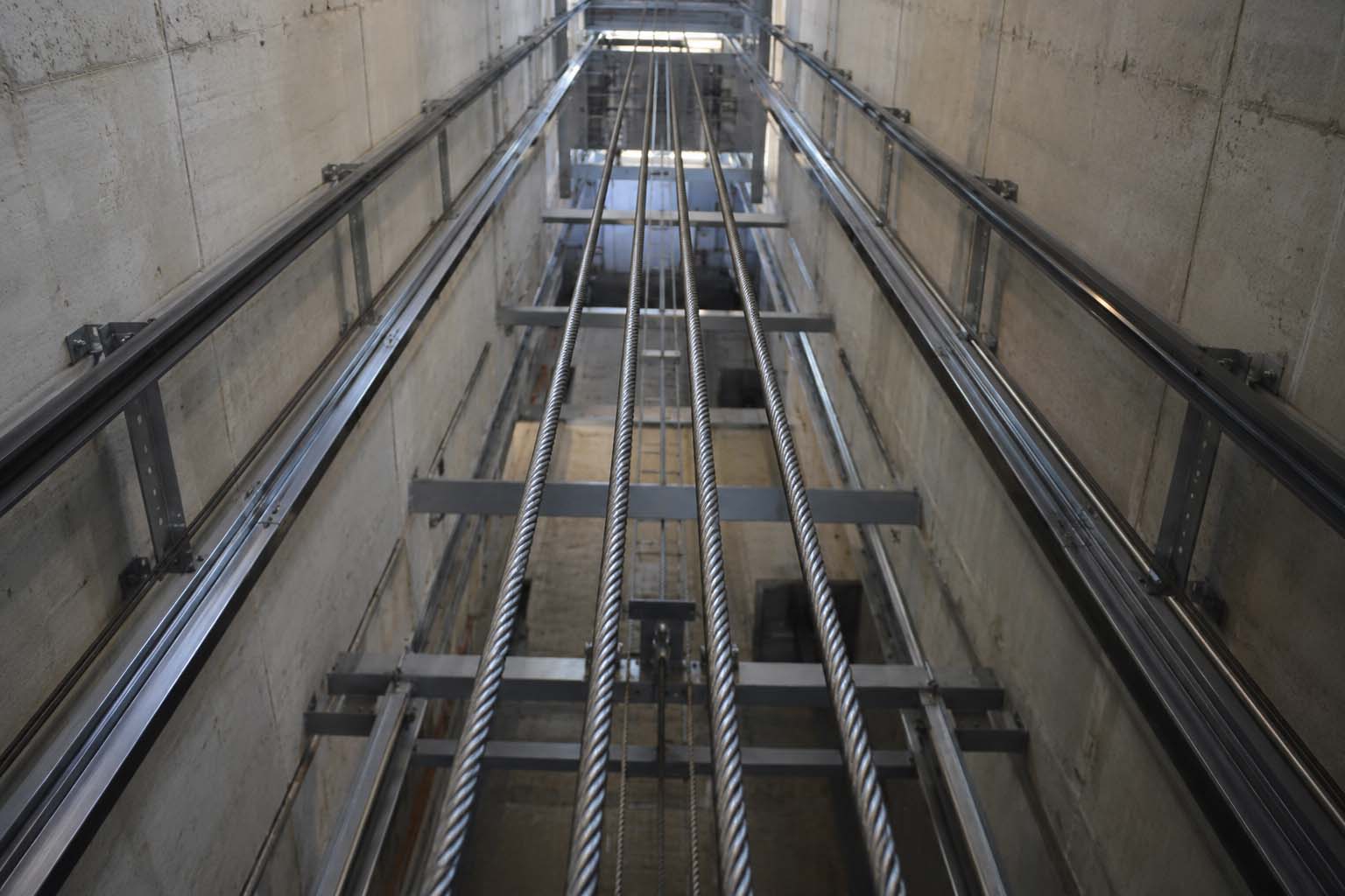
A steel wire rope for elevator usage is classified by its specific mechanical function. Each function requires a distinct structural profile.
1. Traction Ropes (Suspension Ropes)
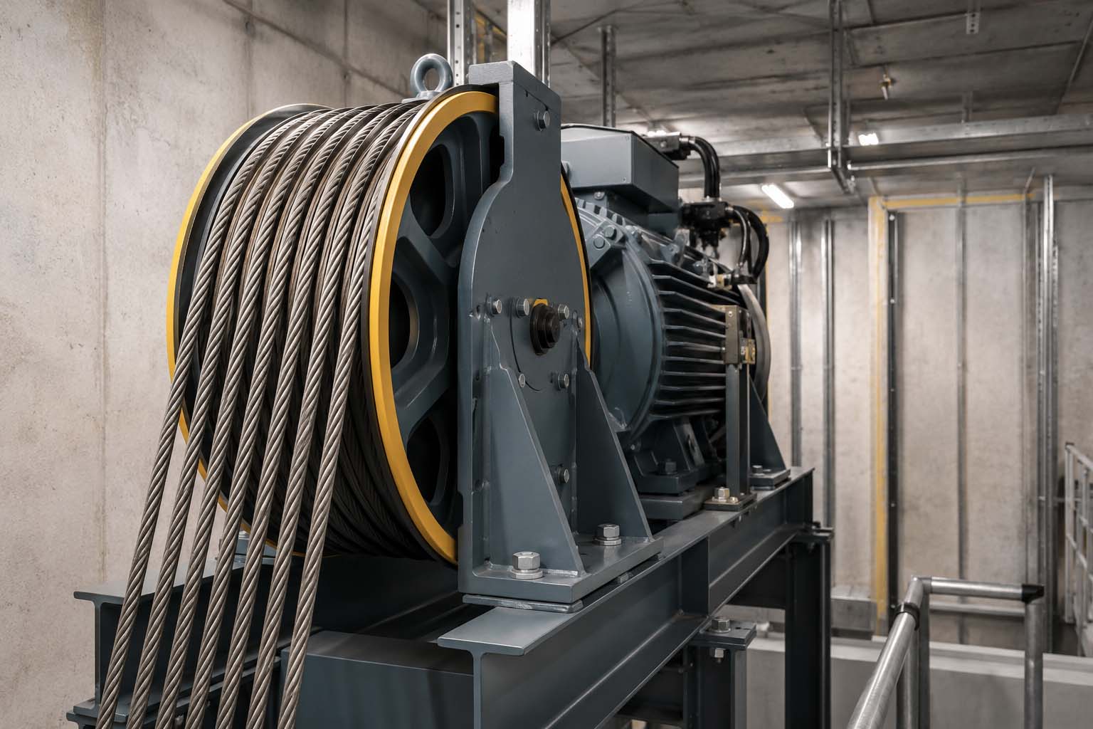
Traction ropes bear the weight of the cabin and counterweight. They run over the motor's drive sheave. Friction between the ropes and sheave grooves moves the system. Traction ropes require extreme bending fatigue resistance, minimal elongation, and precise surface friction coefficients.
2. Compensation Ropes
In buildings exceeding 30 meters, the weight of the traction ropes creates a dynamic imbalance. When the cabin is at the top floor, the counterweight suspends the entire mass of the traction ropes. Compensation ropes attach to the bottom of the cabin and counterweight, looping through a pit tension pulley. They physically balance the traction rope weight, ensuring the motor exerts constant torque.
3. Governor Ropes
The governor rope drives the overspeed safety system. It connects the cabin safety gear to the machine room overspeed governor and a pit tension pulley. It does not bear the cabin's dead weight. If the cabin overspeeds, the governor grips this rope. The resulting tension deploys the cabin brakes. Governor ropes require ultra-low elastic stretch to guarantee immediate brake engagement.
→Applications of Steel Wire Rope in Modern Elevators: An Elevator Wire Rope Guide
Difference Between Elevator Wire Rope and Car Lift Cable
Using an automotive lift cable in a passenger elevator violates safety codes and causes immediate mechanical failure. A wire rope for elevator operates under entirely different engineering parameters than a car lift cable.
1. Cycle Frequency and Fatigue
A commercial elevator executes 1,500 to 2,500 trips daily. Ropes endure high-speed, continuous kinetic bending over sheaves. A mechanic’s car lift operates fewer than 30 cycles daily at slow speeds. Car lift cables are built for static loads, not high-cycle bending fatigue.
2. Friction Mechanisms
Car lifts use drum-winding mechanisms or hydraulic cylinders. The cable winds onto a drum. Elevators use traction friction. The rope merely passes over a sheave. Elevator ropes require 8 or 9 strands for a perfectly round cross-section to maximize surface contact and friction. A standard 6-strand car lift cable (e.g., 6x19) will severely abrade traction grooves and slip.
3. Safety Factors
Passenger elevators require extreme safety margins. Safety codes mandate traction rope safety factors of 10:1 to 12:1. The combined breaking strength must be twelve times the maximum working load. Car lifts operate under 4:1 to 6:1 safety factors due to human supervision and non-passenger cargo.
→Understanding the Difference Between Elevator Wire Rope and Car Lift Cable
Elevator Wire Rope Specifications Standards
Every elevator steel wire rope must comply with international testing and manufacturing codes. Procurement requires verifying these specific standards.
1. EN 81-20 and EN 81-50 (European Standard)
- It mandates a minimum safety factor of 12 for traction drives with three or more ropes.
- It defines the D/d ratio: The sheave pitch diameter (D) must be at least 40 times the nominal rope diameter (d) to limit bending stress.
2. ASME A17.1 / CSA B44 (North American Standard)
This code governs the United States and Canada.
- It strictly regulates core materials and allowable loads.
- It requires permanent metal data tags attached to the rope shackles. Tags must display diameter, minimum breaking strength, manufacturer name, and installation date.
3. ISO 4344 (International Standard)
ISO 4344 outlines manufacturing, laboratory testing, and marking protocols.
- It defines dimensional tolerances (ropes are manufactured slightly oversize, never undersize).
- It mandates tensile strength grades (e.g., 1370/1770 N/mm2 dual tensile).
- It specifies galvanization or dry surface finish requirements based on operating environments.
Elevator Wire Rope Calculations
Wire rope sizing relies on rigid mathematical physics. A steel wire rope elevator system must guarantee traction without premature component destruction.
1. Safety Factor (Sf) Calculation
The static safety factor is the ratio of combined breaking strength to maximum static load.
Sf = (n × MBL) / Tmax
- n: Total number of wire ropes.
- MBL: Minimum Breaking Load of a single rope (manufacturer certified).
- Tmax: Maximum static tension.
Tmax includes the empty car mass, maximum passenger payload, suspended rope mass, and traveling cable mass.
2. Specific Tread Pressure (p)
Tread pressure is the force the rope exerts on the sheave groove. Excessive pressure crushes the rope core and destroys the sheave. Pressure limits depend on groove geometry:
- U-Grooves (Semicircular): Lowest pressure, longest rope life, lowest friction.
- V-Grooves: Highest friction, extreme pinching pressure, shortest rope life.
- Undercut U-Grooves: The standard compromise. The cut bottom forces the rope to contact two points, providing high traction with moderate pressure.
Engineers calculate specific pressure (p) to ensure it remains below the EN 81-50 maximum permissible limits, which are based on sheave hardness and elevator velocity.
3. Euler’s Traction Formula
Traction relies on the tension ratio between the heavy side (T1) and light side (T2) of the sheave.
(T1 / T2) <= e^(f × a)
- f: Apparent coefficient of friction.
- a: Angle of wrap (arc of contact).
This plain-text formula proves the ropes will not slip during emergency braking or maximum load boarding.
→Elevator Wire Rope Calculations: A Simple Safety Guide
Selecting Wire Rope Sizes for Elevator Systems
Choosing dimensions and construction requires matching the rope to the specific motor and hoistway architecture.
1. The D/d Ratio Constraint
The motor's sheave diameter (D) dictates the maximum rope diameter (d). Codes mandate a minimum D/d ratio of 40.
- Example: A gearless motor with a 320mm sheave restricts the maximum rope size to 8mm (320 / 40 = 8). Installing a 10mm rope causes severe bending stress, core collapse, and rapid wire failure.
2. Standard Diameter Mapping
- 6mm - 8mm: Used in Machine-Room-Less (MRL) elevators. MRL systems use compact gearless motors with small sheaves, requiring highly flexible, small-diameter ropes in a 2:1 configuration.
- 10mm - 13mm: The global standard for mid-rise commercial elevators using traditional geared machines in 1:1 roping configurations.
- 16mm - 19mm: Reserved for industrial freight elevators and ultra-high-speed skyscrapers requiring massive Minimum Breaking Loads.
3. Stretch Management (Elongation)
High-rise systems must account for stretch to ensure accurate floor leveling.
- Constructional Stretch: Initial core compression post-installation.
- Elastic Stretch: Dynamic metal stretching based on live passenger loads. For buildings over 20 stories, Independent Wire Rope Core (IWRC) ropes are mandatory. Steel cores minimize stretch, preventing cabin bounce during loading.
Installation Best Practices and Rope Lubrication
A premium wire rope elevator component will fail rapidly if installed improperly or inadequately lubricated.
1. Tension Equalization
When installing multiple ropes (e.g., 5 ropes on one sheave), tension must be exactly equalized. Unequal tension forces one rope to carry the load, destroying that rope and its sheave groove. Technicians must use digital tension meters to balance the shackle springs. Equalization must be re-checked after a 24-hour run-in period. Maximum allowable variance is typically 5%.
2. Anti-Kinking Protocols
Ropes are manufactured with a specific lay (twist). Unspooling must occur in a straight line using a rotating reel stand. Pulling rope over the flange of a stationary spool introduces twists, causing a "kink." A kink permanently deforms the core and strands, destroying load capacity. Kinked ropes must be discarded immediately.
3. Specialized Lubrication
Elevator ropes endure internal kinetic friction. Individual wires slide against each other during bending.
- Factory Lubrication: Fiber cores are impregnated with oil during manufacture, acting as an internal sponge.
- Field Relubrication: Dust and operation dry out the core. Technicians must apply low-viscosity, non-tacky elevator rope lubricant.
- Prohibited Materials: Never use heavy automotive grease. Grease traps abrasive dust, turning into a grinding compound. It fills sheave grooves, causing immediate and total traction slip. Ropes should be slightly oily, never dripping.
Elevator Wire Rope Discard Criteria
Identifying end-of-life criteria is the most critical safety task. Codes like ISO 4344 establish absolute discard thresholds.
1. Broken Wires
Wire breakage indicates severe metal fatigue. Inspection lengths are measured in multiples of the rope diameter (d), typically lengths of 6d and 30d.
- If a technician counts broken wires exceeding the code limit (e.g., 15 breaks in a 30d span) or highly concentrated breaks in one strand, the rope is condemned.
- Valley Breaks: Wires snapping deep between outer strands indicate hidden internal core failure. Ropes with valley breaks require immediate removal.
2. Diameter Reduction
As ropes stretch and cores compress, the external diameter shrinks. Technicians measure diameter from crown to opposite crown using broad-jaw calipers.
- Discard Threshold: A rope must be replaced if its actual diameter reduces by 6% to 8% (depending on local code) from its nominal diameter.
- A 10mm rope measuring 9.4mm is unsafe. Reduced diameter causes the rope to bottom out in the groove, eliminating traction wedge action.
3. Rouging (Fretting Corrosion)
Red or reddish-brown metallic powder on the rope or sheave is "rouging." It is not environmental rust. Rouging is iron oxide dust generated by internal metal-on-metal friction. It proves core lubrication has failed and inner wires are disintegrating. Ropes exhibiting severe rouging must be replaced immediately.
4. Structural Deformations
Any permanent structural geometry change requires replacement. This includes bird-caging (outer strands separating from the core), popped cores, or localized crushing.
5. Magnetic Rope Testing (MRT)
Visual inspection cannot detect internal faults. High-rise and heavy-duty systems use MRT. An electromagnetic device clamps around the rope, detecting internal wire breaks and core anomalies via magnetic flux leakage, providing a precise diagnostic lifespan report.
→Essential Elevator Wire Rope Discard Criteria and Replacement Guide
Elevator Wire Rope Manufacturers
The global supply chain features specialized metallurgical manufacturers. Raw material quality, drawing precision, and lubrication consistency dictate performance.
1. Leading Global Brands
- Pfeifer Drako (Germany): Specializes in engineered ropes for ultra-high-speed and megatall applications.
- Gustav Wolf (Germany): Produces highly reliable standard 8-strand and specialized 9-strand ropes for modernization.
- Usha Martin & Bekaert: Global entities providing high-volume standardized ropes with strict factory QA/QC.
- Premium Chinese Manufacturers: Top-tier Chinese facilities operate advanced European machinery. They produce high-volume ropes strictly meeting EN 81 and ISO 4344, offering high cost-to-performance ratios for commercial buildings.
2. Procurement Evaluation Criteria Do not source based strictly on price. Apply these technical criteria:
- Mill Test Certificates (MTC): Suppliers must provide MTCs documenting Minimum Breaking Load, torsion test data, and chemical composition.
- Inventory Logistics: Elevator downtime is costly. B2B suppliers must maintain large inventories of standard sizes (8mm-13mm) for immediate global dispatch.
- Value-Added Services: Premium suppliers provide precise length cutting, color-coded matching, and pre-swaged terminations (wedge or babbit sockets) to eliminate field labor.
Comprehensive Maintenance and Inspection Schedule
To prevent unexpected failures and comply with safety regulations, facility managers must enforce a strict inspection schedule.
Monthly Inspections:
- Visually inspect the ropes at the drive sheave for early signs of rouging.
- Check the tension of the ropes at the car and counterweight hitches. Adjust shackle springs if variance exceeds 5%.
- Verify the governor rope tension pulley in the pit is rotating freely and is free of debris.
Semi-Annual Inspections:
- Measure the rope diameter using calipers at the most heavily used sections (typically the sections that pass over the sheave when the car is at the main lobby).
- Count broken wires over 6d and 30d lengths. Document the exact number and location in the maintenance log.
- Assess lubrication levels. Wipe a clean finger across the rope; it should leave a faint oil mark. If dry, apply approved low-viscosity lubricant.
Annual Inspections:
- Conduct a full hoistway check at inspection speed. Look for any structural deformations, bird-caging, or core protrusions.
- Perform Magnetic Rope Testing (MRT) on high-rise or heavily utilized systems to detect internal fatigue.
- Inspect sheave grooves for unequal wear. Use a groove gauge. If groove depth varies significantly, the sheave must be re-machined or replaced alongside the ropes.
Conclusion
The elevator wire rope dictates the safety, load capacity, and operational lifespan of vertical transportation systems. Understanding metallurgical anatomy, executing Euler's traction calculations, maintaining strict D/d ratios, and enforcing ISO 4344 discard criteria are absolute requirements for elevator engineering and maintenance.
Whether upgrading a commercial mid-rise or procuring hardware for OEM manufacturing, prioritize certified compliance and exact specifications over initial cost. Adhering to the engineering mathematics, lubrication protocols, and inspection schedules detailed in this guide guarantees safe, efficient, and code-compliant operation.
Secure your vertical transportation infrastructure with certified components. Review our technical catalog of wire rope for elevators, or consult our engineering team for load calculations, termination requirements, and global procurement logistics.
7 Critical Escalator Safety Devices You Must Know for High-Traffic Areas
A Brief History of Wire Elevator Ropes: From Iron to High-Tensile Steel
Related Article

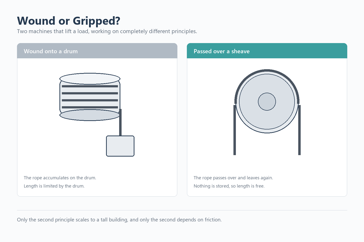
A traction machine does not wind the ropes onto a drum. It grips them.